generic Last reviewed 2026-08-18

BIOS/UEFI firmware

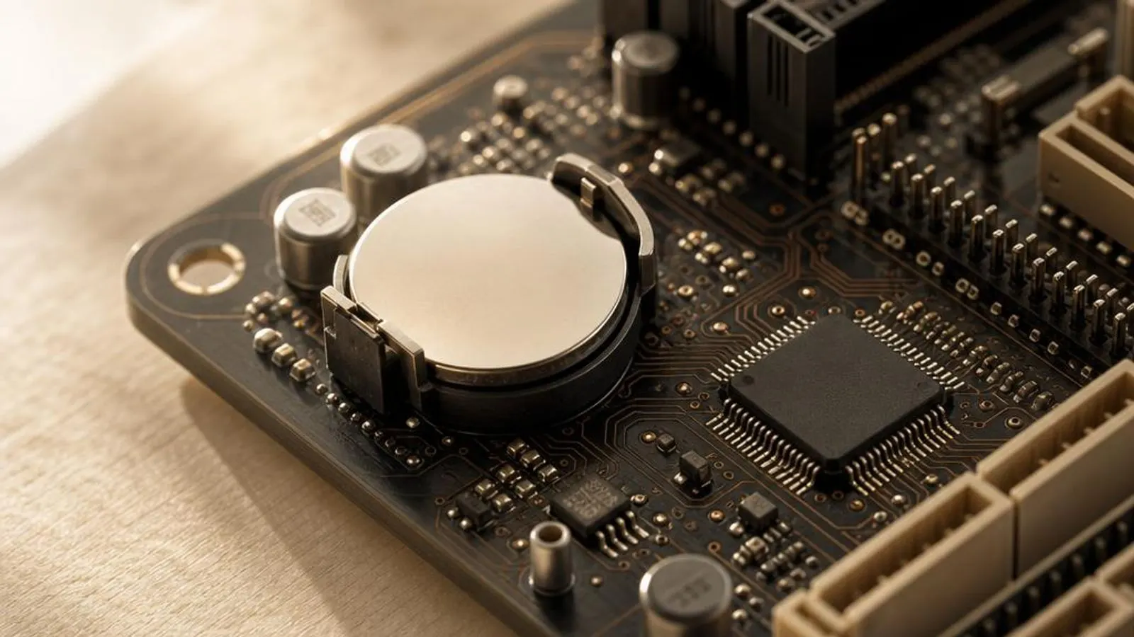
BIOS flash chip on a board (8-pin SOIC) beside the CMOS coin cell shown with socket visible

BIOS/UEFI firmware is the code on the board's SPI flash chip that trains memory, initialises PCIe, and publishes the ACPI tables Windows relies on before the OS ever loads.

Driver Information

Hardware Familysystem storage
Categorybios
OSwin11, win10

In Short

  • UEFI firmware lives on an SPI flash chip on the motherboard and runs the moment power is applied. It trains DDR memory, brings up PCIe and USB, runs the DXE and BDS boot phases, and hands the platform to your bootloader after publishing the ACPI tables that describe power and devices to Windows. Because it precedes the OS, a firmware update is not a normal driver update: a failed flash can leave the board unbootable, so it deserves more care than any in-Windows driver.

What this driver does

BIOS, now almost universally implemented as UEFI, is the first code the processor executes at power-on. It is stored on a small SPI-connected flash chip, typically 16 or 32 megabytes, and it is responsible for turning an inert board into a platform an operating system can load. Everything Windows later takes for granted, working memory, an enumerated PCIe tree, a bootable disk, has already been arranged by firmware before the Windows loader runs. Memory training is the heaviest early task. The firmware reads the SPD chip on each DIMM, applies the timing and voltage the modules request, and runs a training routine that tunes signal delays until the memory bus is stable. On systems using XMP or EXPO overclock profiles the firmware applies those aggressive timings and retrains; a marginal profile is why a machine sometimes takes a long, dark pause on first boot or fails to POST until settings relax. The firmware then executes the standard UEFI phases. The PEI phase initialises just enough to find memory, the DXE phase loads the drivers that bring up PCIe, USB, SATA, and NVMe controllers, and the BDS phase evaluates boot entries and Secure Boot policy before launching a bootloader. Along the way it builds the ACPI tables, the machine-readable description of sleep states, thermal zones, and devices that Windows consumes to manage power and enumerate hardware. UEFI also owns platform security primitives. It stores Secure Boot keys, hosts the firmware TPM on many systems, and enforces the boot-path integrity checks Windows 11 depends on. Because these live in firmware, a setting changed in the UEFI menu, Secure Boot toggled, CSM enabled, fTPM cleared, can decide whether Windows boots at all or whether BitLocker demands its recovery key.

Cutaway view of bios/uefi firmware with major components labelled

Why updating matters

A UEFI update is the only way to change behaviour that happens before Windows exists, and it fixes a distinct class of problems. New CPU microcode ships inside firmware, so support for a processor released after the board, and mitigations for silicon errata, arrive as a BIOS revision rather than a Windows patch. On AMD boards especially, an AGESA update inside a new BIOS routinely improves memory compatibility and fixes fTPM stutter that no OS-level change could touch. Stability and compatibility fixes are common. Revisions correct memory training that failed with certain DIMM kits, repair PCIe link training that dropped a fast NVMe drive to a slower gear, and adjust ACPI tables so sleep and wake behave. Where a board shipped early in a platform's life, later firmware often transforms how many memory kits will run their rated XMP or EXPO profile. Security is a growing reason. Firmware vulnerabilities sit below the operating system, so they are prized targets; vendors distribute patched Secure Boot key databases and close SMM and SPI-flash weaknesses through BIOS updates. Skipping these leaves the most privileged layer of the machine on old, potentially exploitable code. Unlike an in-Windows driver, firmware comes almost entirely from your board or laptop maker's support page for the exact model, and increasingly some vendors also deliver capsule updates through Windows Update. Because a bad flash can brick the board, apply only the firmware built for your precise model and revision, read the release notes, and never interrupt the process.

BIOS/UEFI firmware connected wirelessly and physically to typical peripherals in its ecosystem

Signs a driver may be failing

  • The machine sits on a black screen after a memory or CPU change and only POSTs once XMP/EXPO is disabled
  • A newly released CPU is not recognised until firmware carrying its microcode is installed
  • BitLocker demands its recovery key after a UEFI setting such as Secure Boot or CSM was toggled
  • A fast NVMe drive trains at a slower PCIe generation until a firmware revision corrects link training
  • Windows 11 setup reports the PC does not meet requirements because Secure Boot or fTPM is off in UEFI
  • The system will not enter deep sleep, or wakes immediately, because the ACPI tables are stale

How it fits into the OS stack

Drivers operate in the background, serving as translators. Here is where the BIOS/UEFI firmware sits between your apps and the hardware.

Diagram showing how a bios/uefi firmware driver sits between the application layer and the hardware

Distribution comparison

Vendor Comparison
ProviderFeatures & Stability
Board / laptop maker for your modelThe vendor's support page carries the only firmware image built and validated for your exact board revision, including the matched CPU microcode and AGESA or reference code. This is the authoritative route, and the flashing tool it provides (an in-UEFI updater or a vendor Windows app) is the safest, but images are model-specific and must never be cross-flashed.
Windows Update (UEFI capsule)Some vendors publish firmware as a UEFI capsule that Windows Update stages and applies at the next reboot. This is the lowest-effort route and is signed end to end, but coverage is patchy, it lags the vendor's own releases, and it usually offers only mainstream revisions rather than beta or AGESA-specific builds.
In-UEFI flash utility (BIOS FlashBack / EZ Flash)Most boards include a built-in updater reachable from the UEFI menu, and many enthusiast boards add a flash-from-USB button that works with no CPU or memory installed. This is the most resilient method for recovering from a bad flash, but it depends on you supplying the correct image on a FAT32 drive.

Before you start

1Open Device Manager by right-clicking the Start button.
2Expand the relevant device category for your hardware.
3Right-click the specific component to open Properties.
4Check the current driver version in the Driver tab.
"Only install drivers from your operating system's update tool or the manufacturer's official support page."

Where this driver comes from

Drivers for BIOS/UEFI firmware typically reach your PC through one of three routes: shipped natively with the Windows operating system, delivered dynamically through system updates, or published directly by the hardware manufacturer for your specific model.

To ensure system stability, always allow your OS to handle baseline generic drivers. If you are experiencing performance issues or require advanced control panels, identify the exact model of your hardware and consult the device manufacturer's dedicated support resources.

Fixing installation problems

1

Confirm the current firmware version

Enter the UEFI menu at boot or run msinfo32 in Windows and read the BIOS Version/Date line. Compare it to the versions listed for your exact model so you know whether an update is even the right move before touching the flash chip.

2

Flash with the vendor's own tool

Place the model-specific image on a FAT32 USB drive and use the in-UEFI updater, or run the vendor's Windows flashing app. Let it complete untouched; the board will reboot itself one or more times as it writes and verifies the SPI flash.

3

Reapply and verify settings

After the flash, re-enter UEFI, load optimised defaults, then reapply your XMP/EXPO profile, boot order, Secure Boot, and fTPM settings. Reconfirm the memory posts and trains, and check the NVMe drive reports its rated PCIe generation.

4

Recover a failed flash

If the board will not POST after a flash, use BIOS FlashBack or the dual-BIOS switch if the board has one, supplying the correct image on USB with no need for CPU or memory. This is why an enthusiast board's flash button exists, and it is the intended recovery path.

5

Clear a BitLocker recovery prompt

If BitLocker asks for its key after the update, enter the 48-digit recovery key from your Microsoft account, then suspend and resume BitLocker in Windows so it re-seals to the new firmware measurements and stops prompting.

How to uninstall or rollback

1Click the Driver tab in the properties window.
2Select "Roll Back Driver" to revert to the previous version.
3If greyed out, use "Uninstall Device" instead.
1

Step 1

Check the vendor's page for whether downgrading past a listed microcode or AGESA barrier is permitted; some revisions block it
2

Step 2

Suspend BitLocker so the firmware change does not force a recovery-key prompt on the next boot
3

Step 3

Place the earlier model-specific image on a FAT32 USB drive as before
4

Step 4

Use the in-UEFI updater or the BIOS FlashBack button to write the previous version
5

Step 5

Re-enter UEFI, load defaults, and reapply your memory profile and boot settings once the older firmware is running

Safety Warning

A firmware flash is not a routine update: interrupting the write to the SPI flash chip, or using an image not built for your exact model, can leave the board permanently unbootable. Guarantee stable power and use only the vendor's matched image.

Common error codes

From power-on to bootloader: the UEFI phases

When power is applied, the CPU begins executing firmware from the SPI flash chip. The Security (SEC) and Pre-EFI Initialisation (PEI) phases bring up the cache-as-RAM environment and locate main memory. The Driver Execution Environment (DXE) phase then loads the modular drivers that initialise PCIe, USB, SATA, and NVMe controllers, and the Boot Device Selection (BDS) phase evaluates boot entries and Secure Boot policy before launching a bootloader. This staged design is why UEFI feels like a small operating system in its own right. Each phase can carry vendor and silicon-reference modules, which is how a single BIOS image bundles CPU microcode, AGESA or Intel reference code, and the vendor's own setup interface. It is also why a firmware update can change so many behaviours at once, from memory compatibility to sleep to device enumeration.

Memory training, SPD, and overclock profiles

Getting DDR memory stable is the most delicate early task. The firmware reads each module's SPD chip to learn its rated timings, then runs a training routine that adjusts signal delays and voltages until the bus passes internal checks. Faster modules, higher capacities, and four-DIMM configurations make training harder, which is why a large kit sometimes needs several seconds of dark screen on first boot. XMP and EXPO are stored overclock profiles that ask the firmware to apply timings well beyond the JEDEC baseline. When a profile is marginal or the firmware's memory code is immature, training can fail and the board either refuses to POST or drops back to a safe default. A BIOS revision with improved memory code frequently rescues a kit that would not run its rated profile, which is one of the most common legitimate reasons to update.

ACPI tables and the handoff to Windows

Before launching the bootloader, firmware constructs the ACPI tables, a set of structured descriptions the operating system reads to understand the platform. They enumerate sleep states, thermal zones, embedded controllers, fixed hardware registers, and the wake sources the machine supports. Windows does not probe most of this directly; it trusts the tables the firmware publishes. That trust explains a cluster of symptoms. If the tables describe sleep incorrectly, or a firmware update resets the configured sleep mode, the machine may refuse deep sleep or wake immediately. The powercfg utility in Windows reports which sleep states the current tables actually offer, making it the right tool to confirm whether a firmware change, rather than a driver, is behind a power-management fault.

Secure Boot, TPM, and the Windows 11 baseline

UEFI owns the platform-security features Windows 11 assumes. Secure Boot verifies each stage of the boot path against a key database stored in firmware, refusing to launch unsigned bootloaders. Many systems host their TPM inside firmware, Intel PTT or AMD fTPM, so the same flash chip that trains memory also provides the cryptographic root Windows uses to seal BitLocker keys and prove boot integrity. Because these live in firmware, UEFI settings decide whether Windows 11 will even install. Leaving the board in legacy CSM mode, or with Secure Boot or fTPM disabled, causes setup to reject the machine. The flip side is fragility: toggling any of these changes the measurements BitLocker sealed against, which is why an innocent-looking UEFI edit can trigger a recovery-key prompt on the next boot.

Where this driver comes from

Firmware reaches your PC by three routes, and it is unusual in leaning heavily on one. The first route is shipped with the operating system: strictly, the OS ships no firmware, but Windows carries the loaders and the ACPI and UEFI runtime consumers that expect firmware to have already run, so the platform's own SPI flash image is what greets a fresh install rather than anything Windows provides. The second route is delivered through system updates: some vendors package firmware as a UEFI capsule that Windows Update stages and applies at the next reboot, signed end to end. This is convenient but has patchy coverage and typically offers only mainstream revisions. The third route is published by the hardware maker for a specific model, and for firmware this is the primary one. Your board or laptop vendor builds and validates an image for a precise board revision, bundles the matched CPU microcode and reference code, and posts it with release notes on that model's support page, which this site describes in words rather than links. Because a wrong image or an interrupted write can brick the board, this vendor route demands more discipline than any in-Windows driver: match the model exactly, read the notes, and never interrupt the flash.

Recovering from a bad flash

Firmware is the one component where a failed update can render a machine unbootable, so recovery features exist by design. Many enthusiast boards include BIOS FlashBack, a button that writes a known-good image from a FAT32 USB stick with no CPU, memory, or GPU installed. Others carry dual BIOS, a second flash chip that can restore the first if a write goes wrong. If a board has neither, an incomplete image may require reprogramming the SPI chip with an external programmer, which is beyond most home setups. That asymmetry is the whole argument for caution: stable power, the correct model-specific image, and an uninterrupted write cost nothing, while a botched flash can cost the board. When you do recover, re-enter UEFI afterward, load optimised defaults, and rebuild your memory profile and boot settings before returning to Windows.

Frequently asked questions

Reviewer:
Last Reviewed:

Related Drivers